Multi-Chassis Link Aggregation (MLAG) overview

Cloud computing and other highly virtualized data center applications have placed many new and unique requirements on the data center network infrastructure. Protocol and control mechanisms that limit the disastrous effects of a topology loop are necessary. The Spanning Tree Protocol (STP) is the primary solution to this problem because it provides a loop-free Layer 2 environment. STP has gone through a number of enhancements and extensions, and even though it scales to very large network environments, it still only provides one active path from one device to another, regardless of how many actual connections might exist in the network. Additionally, STP can result in suboptimal communication paths through the network, adding latency and degrading application performance.
To help overcome the limitations of STP, several enhancements have been standardized. These include Multiple STP (MSTP), which configures a separate spanning tree for each virtual local area network (VLAN) and the link aggregation group (LAG) standard (IEEE 802.3ad), which allows two or more physical links to be bonded into a single logical link, either between two switches or between a server and a switch. It is possible for one end of the link aggregated port group to be dualhomed into two different devices to provide device-level redundancy. The other end of the group is still single-homed and continues to run normal LAG. This extension to the LAG specification is called multichassis link aggregation (MC-LAG) and is standardized as IEEE 802.1ax (2008). MLAG implementations are vendor-specific. Say MC-LAG Juniper and mLACP Cisco. Care needs to be taken to ensure that the two switches on the same tier of the network are from the same vendor (switches from different vendors can be used on different tiers of the network).
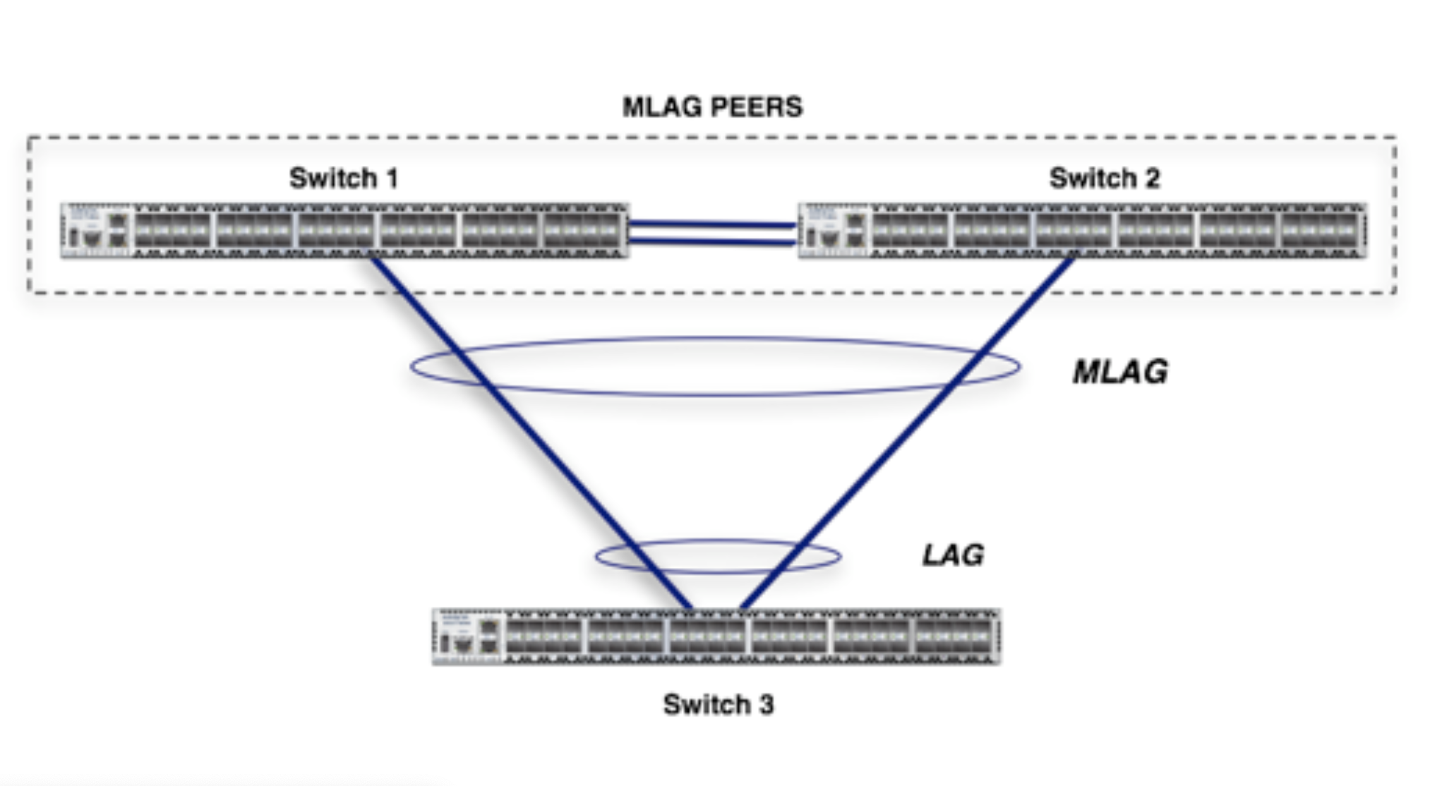
Multichassis link aggregation groups (MC-LAGs) enable a client device to form a logical LAG interface between two MC-LAG peers. An MC-LAG provides redundancy and load balancing between the two MC-LAG peers, multihoming support, and a loop-free Layer 2 network without running STP.

On one end of an MC-LAG, there is an MC-LAG client device, such as a server, that has one or more physical links in a link aggregation group (LAG). This client device uses the link as a LAG. On the other side of the MC-LAG, there can be a maximum of two MC-LAG peers. Each of the MC-LAG peers has one or more physical links connected to a single client device.

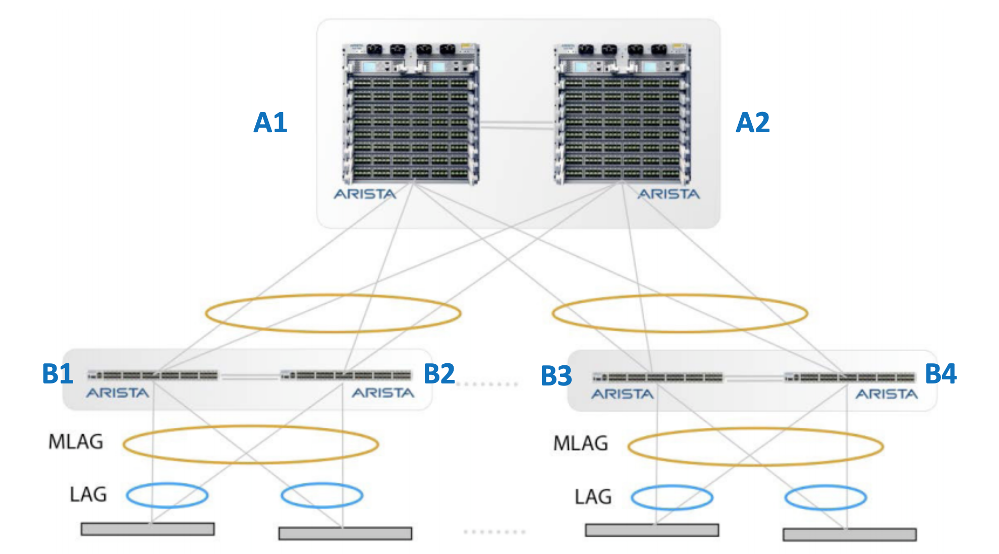
Additionally, you can also connect pairs of MLAG switches to each other in a switch-to-switch MLAG setup. In this case, B1 and B2 are also MLAG peer switches and present a two-port bond from a single logical system to A1 and A2. A1 and A2 do the same as far as B1 and B2 are concerned. For a switch-to-switch MLAG configuration, each switch pair must have a unique system MAC address. In the above example, the switch pair A1-A2 has system MAC address configured which is a different system MAC address than the one used by the switch pair B1-B2. The same case applies for switches B3 and B4.